Mass Balance of a Kiln System
The following diagram illustrates an example of the mass flows in a cement plant and the mass balance of a kiln system from raw meal (RM) to clinker.
Figure 2: Schematic diagram of material and dust flows in a cement plant
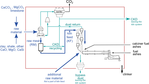
The reporting of CO2 emissions from the calcination of raw materials depends on the principle choice of the method for determining the mass balance: 1. from the input side (raw meal consumption) or 2. from the output side (clinker production).
Accordingly, you need to consider the reporting of the mass flows Bypass dust![]() , cement kiln dust (CKD
, cement kiln dust (CKD![]() ) leaving the kiln system (and crossing the red boundary in the diagram) and additional raw materials (ARM
) leaving the kiln system (and crossing the red boundary in the diagram) and additional raw materials (ARM![]() ), which are not part of the normal kiln feed, as follows:
), which are not part of the normal kiln feed, as follows:
1. Simple input method (A1) and detailed input method (A2): The actual amount of raw meal consumed for clinker production can be determined by weighing the kiln feed and subtracting the Dust return![]() .
.
- Bypass dust leaving the kiln system is accounted for in the amount of raw meal consumed. Additional calculations may be required if the bypass dust is only partially calcined. This is implemented only in the detailed input method (A2): line650
-
CKD recycling remains within the mass balance and therefore does not need additional reporting.
- CKD leaving the kiln system (and crossing the red boundary in the diagram) needs to be quantified and requires additional reporting in the input methods (A1 and A2): line510 or line655
- Additional raw materials (ARM) which are not part of the kiln feed are not accounted for by the amount of raw meal consumed. Thus, they require additional reporting in the input methods. However, the necessary calculations are only implemented in the detailed input method (A2): line610 to line630. The simple input method (A1) should therefore not be used if ARM
 are relevant for the complete reporting of the CO2 emissions.
2. Simple output method (B1) and detailed output method (B2): The amount of clinker production can be determined from calculating the clinker mass balance (see Clinker and Cement Production) or by direct weighing.
- Bypass dust leaving the kiln system requires separate reporting: line022
- CKD recycling remains within the mass balance. Thus, it does not need additional reporting.
-
The mass flow of CKD
leaving the kiln system (and crossing the red boundary in the diagram) needs to be accounted for additionally: line023. - Additional raw materials (ARM) do not need to be accounted for additionally in the output methods, which are based on the clinker production.